
Ultimate RAID Data Recovery Tutorial
This RAID data recovery tutorial is intended for those interested in learning to recover data from failed RAID arrays. It’s impossible to teach everything related to RAID data recovery in a single guide, that would take years to learn. However, we hope this guide will give you the overview you need to get started.
Please enjoy, and if you like it, please take a moment to share this article on your favorite social media site.
Note: Neither Data Medics, it’s members, employees or anyone else affiliated with our company is responsible for the outcome of DIY data recovery attempts.
Proceed at your own risk.
Looking for Professional Service?
Part 1: Background Information About RAID
In this section, we’ll first consider background information about RAID arrays. Even if you think you already understand what a RAID is, you should read this section. It’ll provide details that you need to understand before you can even begin to recover arrays yourself.
What is a RAID array? The acronym RAID originally stood for Redundant Array of Inexpensive Disks. However, today most people would say it refers to Redundant Array of Independent Disks. In the early days of hard drives, the price per Mb went up exponentially with the capacity of the drive. So to attain larger storage capacity and mitigate cost, smaller capacity “inexpensive” disks were combined into various RAID arrays to pool their storage.
RAID offers numerous advantages over single drive storage. Most notably, redundancy, performance and increased capacity of a single logical volume. These three factors form a sort of RAID benefit triangle as you can see on the right. No single RAID type is perfect in the sense of perfectly meeting all of these factors. Certain RAID types, for example, might sacrifice capacity for additional redundancy. Or sacrifice performance to maintain redundancy while maximizing capacity.
To be clear though, the redundancy in RAID is not the same as a backup. Its intention is for uptime rather than backup. Many RAID controllers allow for on the fly rebuilding should a single member disk fail, during which time the server can continue to operate. This makes it well suited to mission-critical operations where downtime is very costly. Traditional RAID, however, will not protect against logical corruption, sabotage, accidental deletion/format of logical volumes, etc. so a good backup plan is still a must for any RAID array with important data,

Understanding RAID Types
Before you can begin to recover data from failed RAID arrays, it’s critical that you understand the different types of RAID arrays. A simple mistake such as assuming the wrong RAID type will have you spinning your wheels forever getting nowhere fast. In this section, we’ll consider the primary RAID types, their features and some tips on how to recognize them in the binary data.
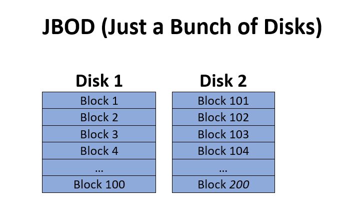
JBOD (Just a Bunch of Disks)
JBOD is the first array type, and probably the simplest as well. Technically it’s not even RAID because it lacks any redundancy. JBOD works by simply merging several physical drives together into a single unit upon which a larger logical volume can be created. Generally speaking, only after the first disk is mostly full will the subsequent disks start to be used. This array type is often referred to as a ‘span’, ‘span array’ or ‘span of disks’ as well.
JBOD can be easily recognized during data recovery because one disk will contain all the filesystem structures and a good amount of data, including large files, which will be able to open if they are contained fully on that first disk. So recovery for JBOD only requires the determination of drive order to be recovered. We’ll get to the specifics of that later.
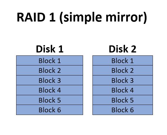
RAID 1 (simple mirror set)
RAID 1 is a simple set of mirrors. It may consist of two or more drives which are simple copies of each other. While the diagram shows “blocks” for simplicity of understanding how data is saved on the disks, no actual specific block size is used for RAID 1.
RAID 1 offers redundancy equivalent to the number of drives in the array. Because each individual drive contains a full copy of the data, RAID 1 is often used for smaller arrays that are used to host the operating system that will boot the server. For example, a typical server might have a RAID 1 of two drives to boot from, then contain another larger RAID 5, 6, 10, or 50 which is used for storing data that will be served. These sort of mixed multiple array setups are something you’ll need to be on the lookout for as you begin to identify the array you’ll be recovering.
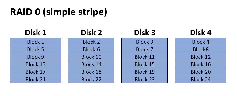
RAID 0
Like JBOD RAID 0 isn’t technically RAID either again because it lacks any redundancy. Technically it’s just AID, not RAID. RAID 0 is a simple stripe array. With this array type a block size is designated, let’s say for example 64Kb. After the first 64Kb is written to Disk 1, the array controller switches to the next disk in the array and write the next 64Kb. This will continue until it reaches the last disk (often referred to as Disk N) after which it’ll repeat.
The advantages of RAID 0 are performance and capacity. The full total capacity of all disks combined is used with no space lost to redundancy. This is generally considered to be the fastest array type as most controllers are capable of writing data to all disks simultaneously, thus multiplying throughput by the number of drives. Data Recovery from a RAID 0 array will require determining two parameters; drive order, and stripe size.
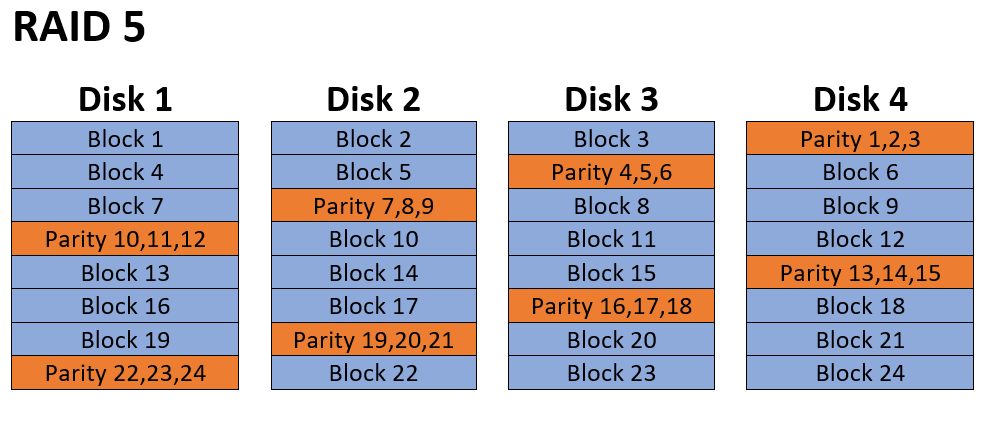
RAID 5
This is one of the most common RAID types implemented in computer servers, and probably the most likely to come in for data recovery. It’s function is similar to RAID 0 in how it stripes data across all disks, but with the addition of a distributed parity block in each row.
Since data ultimately boils down to binary code (ones and zeros) a parity is a simple binary XOR (either or) calculation. It’s essentially just counting even and odd counts of the 1’s.
The obvious advantage of having this parity block is that any single drive can fail and the array will continue to operate. The lost disk can even be rebuilt from the remaining disks. Also, given that it’s a simple XOR this calculation can be done with very little overhead. RAID 5 also makes good use of drive space as only the capacity of a single disk is lost to redundancy regardless of the array size. So an array of 10 x 1Tb hard drives will have 9Tb of effective capacity.
The obvious disadvantage of RAID 5 is that it can’t sustain multiple drive failures. While multiple drive failures might seem unlikely, it really isn’t. Generally, RAID arrays are built out of drives all purchased from the same batch of the same model. They are then operated in the exact same conditions which might include a faulty power supply, inconsistent power, excessive vibration or other factors. So by the time one drive is failing, others may be on the fritz as well. One very common occurrence is that during a rebuild after the first drive fails a second drive will also fail and the array goes down. This is a scenario you’ll need to expect during data recovery, and it highlights the importance of cloning all drives before beginning RAID data recovery operations.
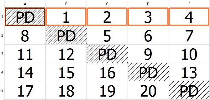
RAID 5 recovery is much more complex than RAID 0 is, as it adds the additional factor of parity and block rotation. RAID 0 only requires to find drive order and block size, but with RAID 5 there are 4 typical methods of block and parity rotation. In the diagram you see an example of left asyncronis parity rotation. So to determine settings using brute force method will take at minimum 4 times as long to accomplish. Also, in some cases there may be a parity delay. We’ll get into more detail on that later.
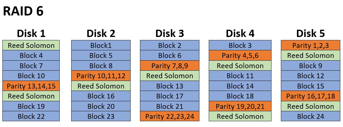
RAID 6
RAID 6 data recovery is probably about the most complex of the standard RAID types, and one best left to professionals with years of experience.
RAID 6 is much like RAID 5, but with the addition of a second redundancy block per row. Typically this extra block is what’s known as a Reed Solomon block. To find out more on Reed Solomon and how the math actually works visit this page which explains it really well: Reed Solomon RAID 6 Math Explained
Suffice to say RAID 6 adds an extra drive worth of redundancy to the array, such that any two drives can fail and the array can continue to operate and be rebuilt with no data loss. It also loses the effective capacity of two drives regardless of the array size. RAID 6 is generally considered to be a slower performing array type as the Reed-Solomon calculation is much more processor intensive than a simple RAID 5 parity is. However, newer high-end RAID cards such as the Areca 1880+ cards can perform the calculation at nearly the same speed as they process RAID 5. Many SAN units, such as EMC, have dumped Reed-Solomon altogether in favor of a sort of diagonal parity better suited to large arrays. So the performance factor isn’t always a major drawback to RAID 6 as it once was early on. In some implementations of RAID 6, there may even be more than two parity / RS blocks per row allowing for even more than two drives to fail while continuing to operate.
RAID 6 recoveries aren’t very common to show up, as they implement so much redundancy. However, as with all things, everything can occasionally fail. If you’re inexperienced with RAID recovery, it’s not recommended to attempt your own RAID 6 recovery. The number of factors to determine quickly becomes astronomically high, and to attempt finding the settings via brute-force is almost always out of the question. RAID 6 recovery requires quite a bit of experience analyzing complex math, XOR, entropy, etc. before the configuration can be determined. These recoveries can often cost tens of thousands of dollars, and take weeks, even for the best data recovery engineers.
Nested RAID
Now we get to some of the more complex RAID types. A nested RAID is essentially just a RAID inside of a RAID.
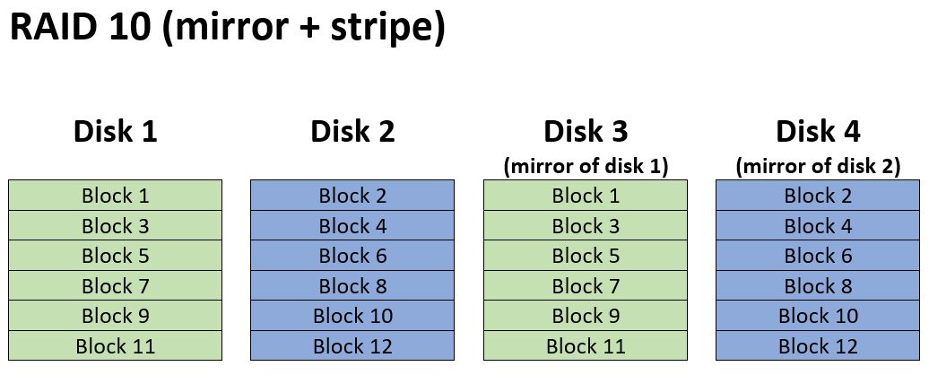
The simplest form of a nested RAID is a RAID 10 or RAID 1+0 (they’re the same thing). As you can see in the image a RAID 10 is a RAID 0 (stripe array) over the top of two RAID 1 mirror arrays. Or you could say it’s a RAID 1 of RAID 0’s. It doesn’t really matter in this particular case which way you want to look at it.
Nested array types can vary greatly in their configuration. For example, a RAID 10 with 12 drives could be configured multiple ways. It could have a quadruple mirror set, with a RAID 0 over
For RAID 10 the simple solution is often to just determine the mirror sets, exclude the extra drives, and then rebuild it as a RAID 0. However, other nested raid types aren’t always so simple. Arrays such as RAID 50, 60, 100 and so on will require determining the settings of the smaller arrays, then to build an array of arrays. It’s not something you’ll want to venture into if you don’t have years of experience. For more information about nested RAID arrays, see this Wikipedia article: https://en.wikipedia.org/wiki/Nested_RAID_levels
Enhanced RAID Types (RAID 5E, RAID 5EE, RAID 6E)
There are also certain non-standard “enhanced” RAID types. These are RAID arrays which include the letter E in the RAID level such as RAID 5E, RAID 5EE and RAID 1E. These aren’t very common, and in some cases, you don’t even need to worry about them. Regarding RAID 5E or 6E, for example, there is just a spare area at the end of each disk which is used as a virtual hot spare. However, for purposes of data recovery, you can simply ignore this spare area and rebuild it as a normal RAID 5 or RAID 6. Other enhanced RAID types such as RAID 5EE and 1E are more complex, but they are also very uncommon and unlikely to show up for recovery.
Parity Rotation
Now, this is something else you’ll need to be aware of when you begin to rebuild RAID arrays that implement a distributed parity (e.g. RAID 5, 6, 50, 60). Parity blocks and data blocks are not always stored in the same linear fashion. There are multiple ways this can be implemented. For RAID 5 there are four variants of parity rotation. Left-synchronous, left-asynchronous, right-synchronous and right asynchronous. You can see them illustrated here:
Left Synchronous
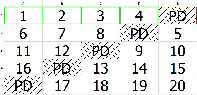
Left Asynchronous
Right Synchronous
Right Asynchronous
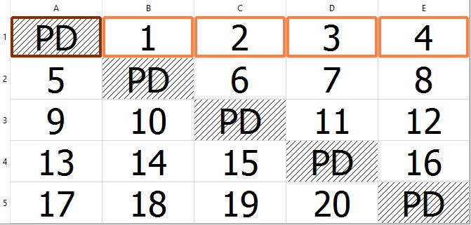
In these images, each disk is represented by a column, and each row is a stripe of data written across the array. The left of right designation has to do with which direction the parity block will shift with each new row, either moving left or right. The
RAID 6 parity rotations are similar, however, there are some added types such as Rotating N Data Continuation and Rotating N Data Restart. There can also be variation in the order of the row parity and Reed-Solomon block locations. Typically row parity is first and Reed-Solomon follows, but in some cases that can be reversed. Also, it’s typical that the two blocks will shift only one disk left or right with each row, but again, there are some cases where it may actually jump two disks with each new row. This is generally referred to as “wide
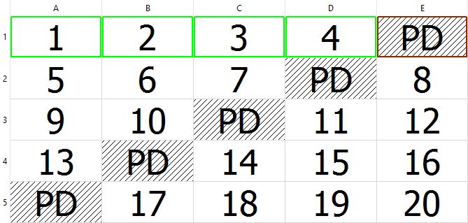
Parity Delay
Another factor you’ll need to be aware of is parity delay. In this image, you can see an example of a parity delay of 4. Parity delay is basically where the system will delay a certain number of stripes before switching which disk the parity is being written too. So as you see in this example with a delay of four, four stripes will be written before it moves the
Most RAID controllers and virtually no software RAIDs support parity delay. However, there are a few brands that do use this. HP and Compaq RAID controllers, for example, will often use a parity delay of 16. It’s something you’ll need to keep in mind as a possibility and it is a reason why you always need to thoroughly research your controller before starting your RAID data recovery.

Part 1 Conclusion
Now that you’ve thoroughly studied the types of RAID arrays out there, you’re better equipped to begin learning how to recover data from them. This section focused on RAID array background information. In part 2 we’ll begin to look into the practical steps required to start recovering data from failed RAID arrays.